
EN 1004-1:2020 Mobile Scaffold Towers: 3T vs AGR Assembly, Load Class 3 & Aluminum Extrusion Procurement Guide
A technical B2B procurement guide to EN 1004-1:2020 mobile access towers, comparing 3T and AGR assembly systems, 6082-T6 aluminum alloys, 2.0mm wall thickness, dual-lock casters, and container logistics.
The Global Transformation of Prefabricated Mobile Access Towers
Prefabricated aluminum mobile access towers represent the standard temporary access solution for commercial MEP contractors, industrial facility maintenance, drywall installation, and facade finishing. However, regulatory frameworks have radically tightened worldwide under EN 1004-1:2020.
For over fifteen years, mobile working towers operated under the legacy EN 1004:2004 standard. That older specification permitted excessive vertical spans between working platforms (up to 4.20 m), completely excluded towers below 2.50 m standing height from collective fall protection rules, and allowed loose components and ambiguous erection sequences that placed erectors at severe fall risk before upper guardrails were pinned.
The implementation of BS EN 1004-1:2020 (and its companion user manual standard EN 1004-2:2021) has fundamentally overhauled access equipment procurement across the United Kingdom, the European Union, the Middle East, and Australasia. Low-level folding podiums (0.0 m to 2.5 m) are now fully regulated; vertical platform intervals are capped strictly at 2.25 m; automatic wind-locks are mandatory on every deck; and caster wheels must feature total-lock dual-action braking capable of resisting 3.0x static proof loads.
For B2B procurement directors, equipment hire fleet managers, and scaffolding importers, purchasing non-compliant legacy stock exposes fleets to instant job-site rejections, contractor safety audits, and severe liability under CDM regulations. This guide breaks down the technical mechanics, metallurgical standards, cost tradeoffs, and quality verification protocols required to source certified aluminum mobile tower containers directly from OEM manufacturers.
Expanded down from 2.5 m to cover all low-level folding units and room podiums.
Maximum vertical distance between consecutive decks (reduced from 4.20 m).
Total-lock castors tested to 3x service load with ≤ 3.0 mm residual permanent deformation.
High-strength extruded tube with 2.0 mm wall thickness and yield strength ≥ 255 MPa.
EN 1004-1:2020 vs Legacy & International Mobile Scaffold Codes
A granular engineering comparison between the current European standard, legacy EN 1004:2004, US OSHA 1926.452(w), and Australasian AS/NZS 1576.3 requirements.
| Engineering Parameter | BS EN 1004-1:2020 (Current) | EN 1004:2004 (Superseded) | US OSHA 1926.452(w) | AS/NZS 1576.3:2015 |
|---|---|---|---|---|
| Regulated Platform Height Scope | 0.0 m to 12.0 m (indoor) / 8.0 m (outdoor) | 2.5 m to 12.0 m (indoor) / 8.0 m (outdoor) | All heights; >10 ft (3.1 m) requires fall protection | 0.0 m to maximum certified height (typ. 12 m / 8 m) |
| Max Vertical Distance Between Platforms | Max 2.25 m (intermediate rest/working decks) | Max 4.20 m (allowed single long ladder climb) | Max 35 ft (10.7 m) between rest levels | Max 2.0 m to 3.0 m depending on territory |
| Ground-to-First Platform Clearance | Max 3.40 m (or 3.40 m from low staging deck) | Max 4.60 m from ground level | Not strictly capped; ladder access mandated | Max 3.0 m from base level |
| Collective Fall Prevention During Erection | Mandatory collective protection (3T or AGR) | Allowed harness or unguarded temporary positioning | Competent person determination / PFAS permitted | Mandatory edge rails before deck occupancy |
| Deck Wind-Lock Catches | Mandatory double-action wind-lock on all decks | Gravity catch or single mechanical clip | Decks must be secured against displacement | Mandatory positive locking against wind uplift |
| Caster Wheel Braking Requirement | Total-lock (simultaneous wheel roll + swivel lock) | Wheel rotation lock only (swivel lock optional) | Wheel lock to prevent movement | Dual-action positive lock for roll and swivel |
| Caster Proof Load Testing Factor | 3.0x SWL static load (residual defl <= 3.0 mm) | 2.0x to 2.5x SWL static load | 4.0x intended working load safety factor | 3.0x rated working load proof test |
| User Manual & Instruction Standard | Mandatory EN 1004-2:2021 compliance booklet | Basic assembly leaflet or stamped label | Manufacturer guidelines / competent person | Specific safe assembly & dismantling manual |
Assembly Methodology Battle: 3T (Through The Trapdoor) vs AGR (Advance Guard Rail)
EN 1004-1 mandates collective fall protection during every phase of erection, modification, and dismantling. Sourcing teams must choose between 3T and AGR frame architectures.
Total Cost of Ownership (TCO) & Operational Comparison: 3T vs AGR Fleet
Data modeled on an 8.2 m working height double-width commercial tower set over a 36-month plant hire operational lifecycle.
| Operational Evaluation Metric | 3T System (Through The Trapdoor) | AGR System (Advance Guard Rail) | Commercial & Procurement Impact |
|---|---|---|---|
| Initial CapEx Cost (8 m Tower Set) | Baseline ($1,650 - $1,950) | +22% to +28% Premium ($2,050 - $2,450) | 3T offers lower capital outlay per container; AGR commands higher rental yield. |
| Component Count (Loose Braces) | 28 - 36 loose horizontal & diagonal braces | 10 - 14 integrated guardrail portal frames | AGR reduces loose component count by 55%, drastically cutting site loss rates. |
| Assembly Speed (2-Man Crew to 8 m) | 35 - 45 minutes per erection cycle | 20 - 25 minutes per erection cycle | AGR achieves ~40% labor time savings, highly prized by industrial turnaround buyers. |
| Erection Fall Hazard Liability | Human dependent (seated in trapdoor) | Engineered passive barrier (zero fall risk) | Tier-1 contractors and major plant hire firms increasingly mandate AGR to eliminate fall citations. |
| Transport & Stillage Volume | Compact brace bundles; high density | Bulkier portal frames; requires custom racking | 3T yields slightly higher container pack density; AGR requires optimized stillage design. |
| Annual Component Replacement Rate | 8% - 14% of loose braces lost or damaged/yr | 2% - 4% of AGR frames damaged/yr | AGR achieves lower 3-year TCO despite higher initial purchase invoice. |
Anatomy of an EN 1004-1:2020 Mobile Scaffold Access Tower
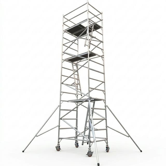
A technical CAD-style engineering illustration showing frame stiles, 3T vs AGR guardrail attachment, platform spacing limits, telescopic outriggers, and dual-action caster brake assemblies.
Structural Schematic: Double-Width Commercial Mobile Tower Assembly
Figure 1: Full engineering topology of an EN 1004-1:2020 compliant commercial aluminum mobile tower with Advance Guard Rail (AGR) frames and dual-action braking casters.
Aluminum Alloy Selection: EN AW-6082-T6 vs 6061-T6 vs 6063-T6
Structural integrity begins at the extrusion press. Sourcing the right alloy temper and true 2.0 mm wall thickness ensures safe load-bearing capacity and long cycle life.
| Alloy Grade & Temper | Yield Strength (Rp0.2) | Tensile Strength (Rm) | Weldability | Corrosion Resistance | Scaffold Application Engineering |
|---|---|---|---|---|---|
| EN AW-6082-T6 (AlSi1MgMn) | >= 255 - 260 MPa | >= 295 - 310 MPa | Excellent (TIG / MIG) | Very High (Marine & Coastal Grade) | Primary structural vertical stiles, ladder frames, outrigger booms |
| EN AW-6061-T6 (AlMg1SiCu) | >= 240 - 245 MPa | >= 290 - 300 MPa | Excellent (Universal) | High (Standard Outdoor Atmospheric) | Global fleet stiles, AGR guardrail frames, horizontal/diagonal braces |
| EN AW-6063-T6 (AlMg0.7Si) | >= 170 - 190 MPa | >= 215 - 230 MPa | Good | Excellent (Smooth Architectural Finish) | Serrated ladder rungs, non-structural toeboard trims only (NEVER stiles) |
| EN AW-6005A-T6 | >= 215 - 225 MPa | >= 255 - 270 MPa | Very Good | High | Platform perimeter side extrusions, trapdoor frame crossbeams |
The 2.0 mm vs Sub-Gauge (1.6 mm / 1.8 mm) Dilemma
Scaffolding stiles use standard outer diameter 50.8 mm (2.0 inch) tubes to interface with standard coupler clamps, outrigger collars, and caster stems. Budget suppliers frequently shave wall thickness down to 1.6 mm or 1.8 mm to reduce raw aluminum weight by 18–22%. However, under EN 1004-1 dynamic wind calculations and rough site transit, sub-gauge stiles exhibit rapid ovalization under outrigger clamp torque, high deflection during heavy tool handling, and permanent bending failure when dropped from truck beds. Genuine 2.0 mm wall thickness in 6082-T6 provides the necessary cross-sectional modulus of elasticity (Z ≈ 3.58 cm³) to withstand harsh industrial rental cycles.
Robotic Fish-Scale TIG Welding vs Cold Crimping
Rung-to-stile connection failure is the leading structural defect identified during third-party factory audits. High-end automated factories employ dual-station robotic TIG or pulsed-MIG welding with 360-degree perimeter penetration, depositing consistent fish-scale beads that resist cyclic shear loads exceeding 5.5 kN per joint. In contrast, mechanical cold-expanded crimped rungs eventually loosen after thermal expansion cycles and repeated vibration, creating hazardous rung rotation under foot. Always mandate destructive weld macro-etching reports in factory FAT milestones.
Trapdoor Platforms, Double-Action Wind-Locks & Total-Lock Casters
Access platforms and rolling caster assemblies represent the primary safety touchpoints for workers. Understanding their mechanical failure thresholds prevents fatal site incidents.
Phenolic Non-Slip Plywood vs Extrusions
Platforms must withstand EN 1004 Load Class 3 (2.0 kN/m², approx. 200 kg/m²) with maximum uniformly distributed capacity of 275 kg. Decks utilize 12 mm exterior-grade birch plywood coated with 220 g/m² phenolic wiremesh non-slip film, or hollow extruded aluminum planks for chemical plant fire safety. Trapdoors must feature heavy-duty piano hinges and stay-open latches.
Class 3: 200 kg/m² Uniform LoadMandatory Double-Action Wind-Locks
Under the revised EN 1004-1 rules, loose decks held only by gravity or single-motion latches are non-compliant. High-velocity wind gusts passing beneath open tower structures create negative pressure (Bernoulli uplift ≥ 0.10 kN/m²). All deck hooks must incorporate positive double-action spring-loaded safety latches at both ends that cannot disengage accidentally without manual intervention.
Double-Action Positive LatchEN 1004 Total-Lock Dual-Action Casters
Castors (typically 150 mm or 200 mm diameter) must feature total lock capability: pressing the foot pedal engages a dual brake shoe that simultaneously locks wheel rolling rotation AND the 360° vertical swivel raceway. The assembly must pass a 3.0x SWL static load test held for 1 minute (residual deformation ≤ 3.0 mm after 30 min) and resist a 0.30 kN horizontal slip force under load.
3.0x SWL Proof Load TestedNever specify smooth push-fit caster stems for commercial hire fleets. EN 1004-1 compliant towers require coarse Acme-threaded solid steel or thick-wall tubular spindle legs with heavy cast adjustment collars. This allows precise millimeter-level leveling over uneven concrete slabs, ramps, and external asphalt gradients (up to 250 mm vertical adjustment) while maintaining structural coaxial alignment with the ladder stiles.
Outrigger Geometry, Aerodynamic Overturning Moments & Ballast Protocols
Mobile towers are tall, lightweight structures susceptible to overturning under lateral working forces and aerodynamic wind drag. EN 1004-1 governs stability through strict calculation formulas.
Freestanding Height Thresholds
EN 1004-1 sets absolute maximum freestanding platform heights without structural wall ties:
- ✓Indoor Use (Zero Wind Environment): Maximum 12.0 m standing height.
- ✓Outdoor Use (Exposed Environment): Maximum 8.0 m standing height.
- ✓Safe Working Wind Speed Limit: Evacuate and dismantle or tie in if winds exceed 12.7 m/s (28 mph / Beaufort Force 6).
Telescopic Outrigger Mechanics
Stabilizers widen the base footprint to satisfy dynamic overturning moment equations (M_restoring > 1.5 × M_overturning). Outriggers must feature:
- ✓Dual high-tensile cast aluminum wing-nut couplers clamping securely to 50.8 mm stiles.
- ✓Telescopic lower leg extension with positive spring-pin positioning.
- ✓Articulating swivel footpads with ribbed non-slip vulcanized rubber bases.
Mandatory EN 1004-1 Ballast Regulation:
If structural calculations dictate ballast weights to prevent wind overturning, ballast must be securely clamped directly onto the tower base chassis. Strict Compliance Warning: Under EN 1004-1:2020 Clause 7.3, loose bricks, concrete rubble, or unsecured aggregate sandbags are strictly non-compliant. Ballast must consist of factory-certified solid cast iron weights or certified rigid containers with tamper-proof mechanical locking clamps.
B2B Container Optimization: 40ft High Cube Stillage Staging
Aluminum towers are lightweight and bulky. Mastering cubic packing efficiency and stillage crate engineering is the key to lowering landed freight cost per unit.
Accommodates 32 to 38 complete 8.2 m double-width tower sets (or 65+ single-width indoor units), utilizing approx. 68–72 m³ and weighing 9,500–11,500 kg.
Accommodates 14 to 16 complete 8.2 m double-width towers. Ideal for trial fleet orders or mixed shipments containing dense steel couplers and casters.
Pre-engineered stackable steel stillages for ladder frames (25 frames per stillage) allow rapid forklift offloading in 45 minutes, preventing ocean transit scuffing.
Ocean Freight Protection Best Practices:
- •Protective PE bubble wrap and corner guards on all ladder frame stile spigots.
- •Heavy-duty polyester strapping on brace bundles (color-coded for quick site sorting).
- •Platform decks stacked flat on wooden pallets wrapped in UV-resistant shrink wrap.
- •Caster wheels and adjustable spindles packed in reinforced plywood crates with desiccant packs.
B2B Factory QA Audit Checklist for Overseas Scaffolding Shipments
A comprehensive 6-step testing protocol for procurement engineers and third-party inspection agencies (SGS, TÜV, BV) prior to commercial container release.
Extrusion Caliper & Ultrasonic Test
Verify vertical stiles meet outer diameter 50.8 ± 0.2 mm and wall thickness ≥ 2.0 mm across 10 random frame samples. Measure rung wall thickness (≥ 1.8 mm).
Rung Weld Shear & Tensile Pull-Off
Execute hydraulic tensile pull-off test on rung-to-stile welds. Joint must withstand minimum 5.5 kN vertical shear without weld rupture or stile tearout. Verify weld macro-etching.
Platform Deck Deflection Test
Apply uniformly distributed load of 2.0 kN/m² (200 kg/m²) across trapdoor deck. Measure elastic deflection at midspan (δ ≤ L/100, max 25 mm). Confirm zero permanent sag.
Caster 3x SWL Proof & Brake Slip
Lock caster dual-action brake. Load to 3.0x SWL (1,800 kg for 600 kg rating) for 1 minute. Verify residual deformation ≤ 3.0 mm after 30 min. Apply 0.30 kN horizontal slip test.
Double-Action Wind-Lock Catch Test
Simulate upward aerodynamic suction on platform ends. Verify dual-action latches hold deck securely without dislodging under upward force exceeding 0.50 kN per hook.
EN 1004-2:2021 Manual & Stamping
Verify laser-etched permanent markings on stiles (Manufacturer, EN 1004-1:2020, Load Class 3, Year/Month). Ensure full EN 1004-2 user assembly manual is packed with each tower set.
Frequently Asked Procurement & Engineering Questions
Direct, practical answers to complex B2B sourcing inquiries regarding EN 1004-1:2020 mobile scaffold tower compliance, fleet standardization, and container importing.
- •BSI / CEN (BS EN 1004-1:2020): Mobile access and working towers made of prefabricated elements. Materials, dimensions, design loads, safety and performance requirements. BSI Standards Catalog
- •PASMA (Prefabricated Access Suppliers' & Manufacturers' Association): Technical Guidance on EN 1004-1:2020 Changes, 3T vs AGR Selection, and Operator Safety Protocols. PASMA Standard Hub
- •US OSHA (29 CFR 1926.452(w)): Safety and Health Regulations for Construction - Mobile Scaffolds. OSHA Safety Regulations
- •Standards Australia / NZ (AS/NZS 1576.3:2015): Scaffolding - Prefabricated and tube-and-coupler scaffolding - Prefabricated mobile access and working towers. Standards Australia Catalog
Procuring Certified EN 1004-1:2020 Aluminum Mobile Tower Fleets?
Scaffolding Wholesale manufactures and exports heavy-duty EN AW-6082-T6 aluminum mobile scaffold towers in both 3T and AGR configurations. Stop risking project compliance delays or rental fleet rejections with sub-gauge tubing. Contact our engineering export desk with your target working heights and container volume for verified third-party test certificates, custom stillage options, and factory-direct pricing.
Recommended Container Quote Specification Checklist:
- ✓Width preference: Single Width (0.85 m) or Double Width (1.45 m); Platform length (1.8 m or 2.5 m)
- ✓Assembly methodology: 3T (Through The Trapdoor) or AGR (Advance Guard Rail) modular portal frames
- ✓Target working heights: 4.2 m, 6.2 m, 8.2 m, 10.2 m, or 12.2 m complete tower packages
- ✓Caster specification: 150 mm or 200 mm dual-lock total-brake with adjustable Acme spindle stems
- ✓Container destination port & logistics terms (FOB Ningbo / Shanghai, CIF, or DDP)