
Scaffolding Wall Ties & Façade Anchoring Technical Sourcing Guide: Tie Duty Ratings (6.1 kN vs 12.2 kN), 6 Structural Tie Typologies, NASC TG4:19 Proof Testing & Cladding Wind Loads
Compare scaffold wall ties, anchor types, cladding loads and TG4/OSHA requirements. Use the inspection checklist to prepare a documented wholesale hardware RFQ.
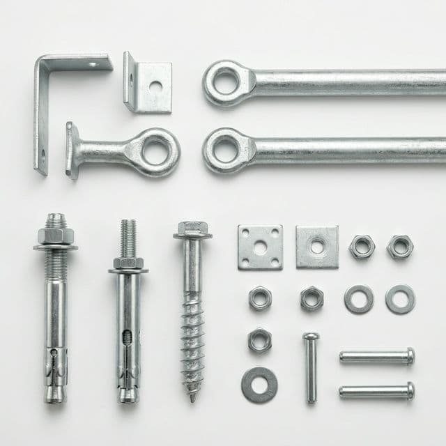
Select Scaffold Wall Ties by Load Path, Substrate & Site Design
Scaffold wall ties transfer lateral loads between the scaffold and the building. For wholesale buyers, a 6.1 kN or 12.2 kN requirement must be matched by the complete approved connection, including the anchor, tie tube, couplers and substrate. Start with the designer’s tie schedule before ordering interchangeable-looking hardware.
Scope: procurement of supported façade-scaffold ties for global buyers. US OSHA rules, UK/European design documents and Australian guidance have different roles and jurisdictions. Hoist mast anchors, suspended access and bespoke structural connections need their own specialist design. This editorial guide supports RFQ preparation; project approval remains with the responsible designer.
Reviewed by the Scaffolding Wholesale Desk. No first-party load tests or measured product capacities are claimed. Check the contractually applicable standards editions and local requirements before use.
Specify the force and load basis; require assembly evidence.
Netting and sheeting require a documented wind-load review.
Agree sampling, load, acceptance criteria and failure actions.
Scaffold Tie Duty Ratings: Standard (6.1 kN) vs Heavy Duty (12.2 kN) vs Structural
Compare specified tie demands with the resistance of the entire connection. BS EN 12811-1, applicable TG20 guidance and manufacturer data must be applied within the project design; no single hardware property establishes the assembly rating.
Technical Parameter Matrix: Scaffold Façade Tie Duty Classifications
Use this six-row procurement matrix to identify the evidence required for each connection. The headings describe RFQ categories, not universal product load ratings or permitted tie grids.
| Engineering Parameter | Light / Restricted Use | Standard: 6.1 kN Demand | Heavy: 12.2 kN Demand | Structural / Engineered |
|---|---|---|---|---|
| RFQ force requirement | Use the approved design value | 6.1 kN when specified by the design | 12.2 kN when specified by the design | Project-specific node reactions |
| Connection evidence | Approved friction or positive connection detail | Declared coupler data plus assembly detail | Approved higher-capacity assembly detail | Bracket, bolt and building calculations |
| Cladding suitability | Only within documented design limits | Verify the actual netting or sheeting specification | Higher duty alone does not approve sheeting | Include cladding and concentrated loads |
| Tie spacing | Approved tie layout | Compliance sheet or project design | Compliance sheet or project design | Engineered locations and reactions |
| Anchor testing plan | Designer-approved scope and acceptance criteria | Verify applicable TG4 edition and anchor instructions | Verify applicable TG4 edition and anchor instructions | Connection-specific inspection and testing plan |
| Failure checks | Friction loss and unintended movement | Anchor, tube, couplers and substrate | Anchor, tube, couplers and substrate | Steel connection and building load path |
Cladding Wind Loads: What Changes When Nets or Sheeting Are Added?
Cladding changes the exposed area, aerodynamic behavior and force distribution. Ask the designer to check the actual product, site exposure and scaffold geometry before fitting or substituting nets, sheets or banners.
For RFQ screening, a useful arithmetic relation is net pressure multiplied by tributary area. The pressure and load distribution must come from the applicable wind model and scaffold design; mesh openness alone cannot supply them.
Worked example (assumed inputs): 0.50 kN/m² × 12 m² = 6.0 kN. If the assumed net pressure becomes 1.00 kN/m² with the same area, the result becomes 12.0 kN. These are reproducible arithmetic examples, not measured wind loads or an approved tie layout. Actual reactions depend on load sharing, corners, openings, geometry and design factors. The calculation does not approve either a 6.1 kN or 12.2 kN product assembly.
Request the cladding supplier’s aerodynamic data and pass it to the scaffold designer. Record the approved product and fixing pattern so a later substitution triggers a review.
| Cladding System | Product Data to Request | Wind Review Input | Tie Layout Check | Connection Check | Engineering Safeguard |
|---|---|---|---|---|---|
| Unclad Open Tubular Lattice | Member geometry and exposed elevation | Site wind and scaffold force model | From approved unclad layout | Match calculated reactions | Record the unclad design basis before alterations |
| Light Debris Netting | Product identity and tested aerodynamic data | No universal multiplier from mesh openness | Recheck the layout for this product | Confirm each connection against revised reactions | Approve netting before installation |
| Heavy Debris Netting | Permeability, fixing pattern and overlap | Allow for blockage and project exposure | Project-specific corner and edge checks | Use the revised design schedule | Control substitutions and accumulated debris |
| Reinforced Scaffold Sheeting | Sheet dimensions and fixing-system data | Designer-selected pressure and force model | Approved sheeted-scaffold layout | Verify tension and inward restraint | Agree inspection and adverse-weather procedures |
| Heat Shrink-Wrap | Enclosure geometry and openings | Include external and internal pressure effects | Site-specific design or applicable system guidance | Approved ties and building connections | Review enclosure changes with the designer |
| Acoustic / Advertising Banners | Banner area, location and attachment points | Assess local loads at banner fixings | Check the affected nodes and surrounding scaffold | Confirm concentrated reactions | Obtain approval before attaching banners |
Structural Anatomy of a Heavy-Duty Façade Tie & Anchor Assembly
An effective scaffold tie must resist multi-directional forces: tension (wind suction pulling the scaffold away) and compression (wind buffeting pushing the scaffold inward). Examine the mechanical load path below.
Conceptual Load Path: Anchor, Tie Tube, Coupler & Inward Restraint
Concept only: the diagram shows possible load-path elements. Final connection geometry, coupler positions, member sizes and bearing details must follow an approved assembly drawing; the illustration establishes no component or assembly rating.
Comparative Engineering of the 6 Façade Tie Typologies
Every building facade presents distinct structural boundaries—from modern glazed curtain walls and solid reinforced concrete to century-old historical brickwork. Select the correct physical tie typology to prevent jobsite delays and anchor failures.
| Tie Typology | Load Capacity | Best Substrate Fit | Primary Advantages | Critical Failure Risks | Approval Checks |
|---|---|---|---|---|---|
| Through Tie (Opening / Window) | Assembly-specific tension and compression | Structurally suitable wall openings | Can avoid a drilled fixing in the outer face | Spreader bending, bearing failure, loose packing | Approve opening strength and internal access |
| Box Tie (Column / Pier) | Depends on geometry and coupler arrangement | Verified structural columns or piers | Can connect around an existing structural member | Slip, local damage and incomplete restraint | Use an approved detail and protective packing |
| Mechanical Anchor / Ringbolt | Product and substrate-specific resistance | Only base materials covered by the anchor approval | Repeatable installation with the specified tools | Edge breakout, wrong embedment or incomplete setting | Verify substrate, distances and site-test plan |
| Injection Resin Anchor | Product and substrate-specific resistance | Approved concrete or masonry applications | May suit masonry where an expansion fixing does not | Poor hole cleaning, wrong sleeve or incomplete cure | Follow product approval, temperature and cure limits |
| Reveal Tie (Friction Prop) | Friction-dependent; requires explicit design acceptance | Verified structural reveals | Can avoid drilling where its use is permitted | Vibration, packing shrinkage and accidental displacement | Check applicable limits; do not assume use on clad scaffolds |
| Lip / Parapet Tie | Bracket and parapet-specific resistance | Verified load-bearing upstands or parapets | May provide a connection near roof level | Parapet overturning, local cracking or bracket slip | Verify parapet strength and waterproofing detail |
NASC TG4:19 Anchor Testing: What to Put in the Project Plan
Obtain the contractually applicable TG4 edition, anchor instructions and designer’s requirements before testing. Use this workflow to agree the scope and records; take numerical test requirements from the approved project documents.
Resolve Unknown Base Materials Before Ordering
- Identify representative substrate types, locations and installation conditions.
- Agree sample size, test method and how results establish the design resistance.
- Separate sacrificial suitability tests from anchors intended to remain in service.
- Record the anchor model, embedment, distances, installation method and failure behavior.
Verify Installation Against Written Acceptance Criteria
- Approve sampling, proof load, hold time, movement limits and failure escalation before testing.
- Use suitable calibrated equipment and reaction supports that do not invalidate the test.
- Log tested anchor locations, installation records, applied loads and acceptance decisions.
- Refer failures to the responsible designer before relying on the affected anchorage.
For UK inspection context, HSE’s scaffolding FAQ explains competent inspection and reports, including after modification. A tag supplements the report and does not replace it. International orders must also meet the destination’s local inspection and design requirements.
Scaffold Anchoring Hardware & Coupler Examples
Use these catalogue images to identify hardware families for an RFQ. Appearance does not establish material grade, certification or load capacity; request the exact product documentation.
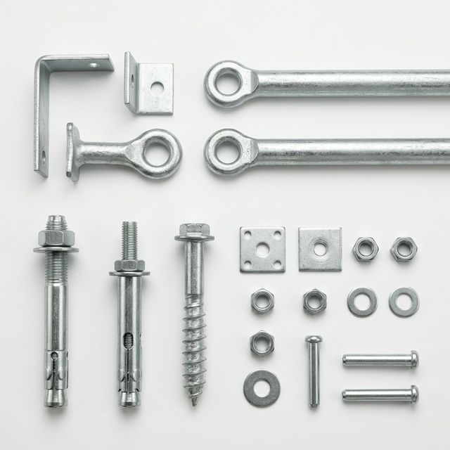
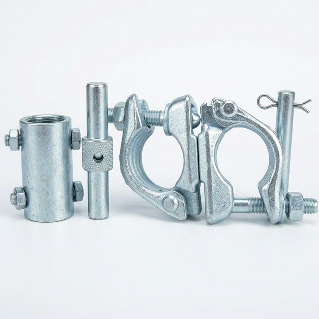
Complete the connected specifications using the scaffold coupler comparison, scaffold tube standards guide and mill certificate verification checklist.
B2B Sourcing & Pre-Shipment Inspection Checklist
Use these six checks for product acceptance and the site-verification handoff. Keep shipment release separate from permission to use installed anchors on a scaffold.
1. Anchor Identity & Batch Traceability
Match manufacturer, part number, ringbolt geometry, thread and batch marking to the approved schedule. Request material and product-performance documents. Check the actual hook or connector fit; do not assume a 48.3 mm tube passes through an anchor eye. Record cracks, thread damage and dimensional deviations.
2. Substrate Approval & Installation Equipment
Check the anchor approval for the actual concrete or masonry, including hollow units where relevant. Confirm embedment, edge distances, spacing, drill size, setting tool, hole-cleaning method and resin cure conditions. A generic M12/M16 sleeve is not evidence of suitability.
3. Coupler Performance & Assembly Detail
Request the declared EN 74-1 class and product test evidence where specified. Match tube diameter, condition and the exact primary/check-coupler arrangement to the approved drawing. Use manufacturer-specified installation torque; do not infer a 12.2 kN assembly rating by adding two individual ratings.
4. Tie Tube Dimensions & Condition
Record outside diameter, nominal wall thickness, length, grade and tolerances against the order. Check wall thickness at representative accessible locations or with suitable calibrated equipment. Inspect corrosion, dents and unsupported length; the designer must verify compression buckling.
5. Coating & Thread Compatibility
Specify finish, applicable coating standard and acceptance criteria in the order. Measure coating thickness using suitable equipment and confirm thread fit after coating. Corrosion exposure, galvanizing suitability and any installation restrictions must be agreed for the chosen anchor system.
6. Site Testing & Release Records
Keep factory acceptance separate from on-site anchorage verification. Obtain the approved preliminary/proof-test plan, tester calibration record, anchor-location log, applied loads and acceptance results. Sampling, hold time and failure escalation must follow the project specification and applicable guidance before release for use.
Frequently Asked Questions: Scaffolding Wall Ties & Façade Anchors
Clear, direct technical answers to critical engineering, safety inspection, and procurement challenges encountered on commercial jobsites.
What should a scaffold wall-tie RFQ include?
State the destination jurisdiction, scaffold system and geometry, cladding, design tie reactions in tension and compression, load basis, substrate, approved connection drawing, quantities and delivery terms. Request traceable product evidence and a site-test plan before approving substitutions.
Does adding a second coupler turn a 6.1 kN tie into a 12.2 kN tie?
Not automatically. These values can be specified tie demands, but the approved assembly must satisfy them. Coupler arrangement, anchor resistance, tube condition, compression restraint and building capacity all matter. Obtain the manufacturer’s data and designer acceptance for the exact configuration.
Can an unclad scaffold tie layout be used after adding netting or sheeting?
Only after checking that the existing design explicitly covers that cladding. Product aerodynamic data, site wind, scaffold geometry and local reactions govern the review. There is no universal wind multiplier or safe area-per-tie conversion for all nets and sheets.
How should buyers specify NASC TG4:19 anchor testing?
Identify the contractually applicable edition and obtain its full requirements through the project team. Agree preliminary suitability testing separately from proof testing of installed anchors. Record sample size, test load, hold time, acceptance criteria and failure actions in a written plan. This guide does not reproduce or independently verify the licensed TG4:19 procedure.
Can reveal ties be substituted for positive anchors?
Only when the applicable scaffold guidance and approved design permit that exact arrangement. Reveal ties depend on friction and can lose restraint through movement, vibration or packing shrinkage. Do not substitute them for positive anchors or use them on clad scaffolds without explicit design acceptance.
What does OSHA 1926.451(c)(1) require for supported scaffold ties?
In the US rule, supported scaffolds exceeding a 4:1 height-to-base-width ratio need restraint. Follow manufacturer recommendations or the specified first-restraint position and spacing: at most 20 ft vertically for scaffolds up to 3 ft wide, or 26 ft for wider scaffolds, and 30 ft horizontally with restraints at both ends. Check the top-restraint and eccentric-load provisions too. These US provisions do not replace UK/European design requirements.
Are resin anchors always required in hollow brickwork?
No. Use an anchor system explicitly approved for the actual base material and loading. Some resin systems require a specified mesh sleeve, but cure conditions, embedment, cleaning and local masonry strength remain critical. Do not substitute a generic resin or expansion anchor based only on thread size.
What happens if an installed anchor fails a proof test?
Record the failure and prevent reliance on the affected anchorage pending competent review. Notify the responsible scaffold designer and site coordinator, investigate the substrate and installation, and apply the approved plan for additional testing and remedial work. A stronger-looking replacement is not sufficient evidence for release.
Sources & Applicable Design Documents
Public sources checked on 31 October 2026. Each has a different jurisdiction and purpose.
- OSHA 29 CFR 1926.451: US supported-scaffold restraint provisions in (c)(1), including first and top restraint, vertical/horizontal intervals and eccentric loads. These provisions do not establish a generic anchor kN rating.
- HSE: Scaffolding FAQ: UK competence, inspection reports and the supplementary role of scaffold tags. It is not a source of TG4 anchor-test factors.
- Safe Work Australia: Guide to Scaffolds and Scaffolding: official guidance index for workplace risk management, published 19 March 2020. Confirm enforceable requirements with the relevant state or territory regulator.
Project documents to obtain separately: applicable editions of NASC TG4 (the title’s TG4:19 reference requires a contract-edition check), TG20, BS EN 12811-1 and the selected anchor/coupler instructions and approvals. The TG4:19 and TG20:21 NASC URLs supplied with this article were inaccessible during review; their full numerical procedures were not independently verified. Require those documents before finalizing the site-test or tie-layout plan.
Procuring Wholesale Scaffold Anchors, Eyebolts & Couplers?
Send Scaffolding Wholesale your approved tie schedule, anchor-system requirements, coupler details, quantities and destination. Request matching product documentation and a quotation for a consolidated hardware shipment. Product supply and site engineering approval are separate steps; agree the design and testing responsibilities before releasing an order.
Recommended Anchor & Tie RFQ Specification Checklist:
- ✓Design basis: destination rules, tension/compression reactions, load basis, cladding and approved tie layout
- ✓Anchor system: exact product, substrate, embedment, thread, edge distances and installation instructions
- ✓Couplers: declared class and performance, assembly drawing, compatible tubes and installation torque
- ✓Finish and traceability: agreed coating specification, inspection criteria and batch documentation
- ✓Tie tubes and site testing: dimensions, grade, unsupported length and approved preliminary/proof-test plan
- ✓Shipment: item quantities, packing, destination port, delivery terms and requested delivery date