
Temporary Edge Protection Systems: BS EN 13374:2025 Class A, B & C Mesh Barrier Procurement Guide
Compare temporary edge protection systems by EN 13374 class, fixing evidence and shipping checks. Use the procurement checklist to prepare your supplier RFQ.
Standards & Compliance
Temporary Edge Protection Systems: Start with the Application
For contractors, engineers and wholesale buyers, the first decision is the protection function and installation context. Compare complete systems before comparing panel prices.
Temporary edge protection systems must suit the working surface, foreseeable fall or slide, supporting structure and destination requirements. For an RFQ, identify the complete panel, post, retention device and base assembly, then request evidence for that configuration rather than a generic “EN compliant” label.
BSI lists BS EN 13374:2025 as published on 31 May 2025. Its scope includes temporary systems on flat and inclined surfaces during construction or maintenance. It excludes scaffold side protection governed by EN 12811-1 or EN 1004-1, public-access barriers and vehicle-impact protection.
Scope and review date: Global English-language procurement guidance, reviewed 27 October 2026. This is a document screening framework, not a system test, installation design or destination compliance certificate. Numeric acceptance limits must come from the current licensed standard, applicable local requirements and the offered system instructions.
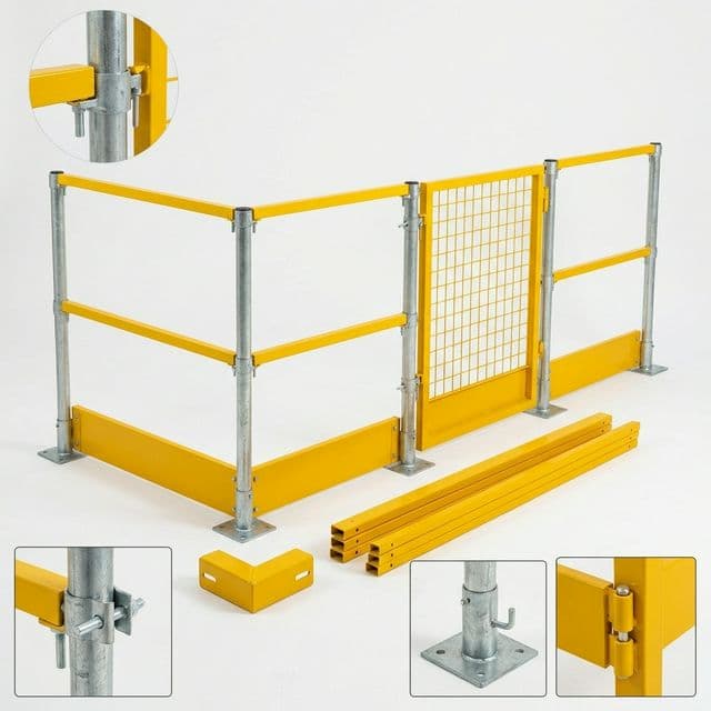
The lead photo illustrates guardrails and a mesh gate; it does not identify a tested class or a slab-clamp configuration. Compare the edge protection product options against the evidence checklist below, or send your layout for a documented RFQ.
Structural Classifications
Understanding BS EN 13374: Class A, Class B, and Class C
The standard categorizes temporary edge protection into three distinct performance classes based on the inclination of the working surface and the kinetic energy profile of potential worker falls.
Class Selection and Procurement Evidence Matrix
Use this screening matrix to decide which documents to request. It does not reproduce the standard’s numerical acceptance criteria.
| Engineering Parameter | Class A (Static) | Class B (Static + Dynamic) | Class C (Higher Dynamic) |
|---|---|---|---|
| Working surface screening | Flat or low pitch | Inclined surface with sliding risk | Steeper surface with higher sliding energy |
| Protection function | Static protection | Static and dynamic protection | Higher dynamic energy absorption |
| Required performance evidence | Static verification for offered assembly | Static and dynamic reports for offered assembly | Dynamic report and support reactions |
| Component retention | Document panel, post and toeboard retention | Check retention in the tested configuration | Check retention during the dynamic event |
| Openings and joints | Check installed gaps against approved requirements | Include post-impact opening evidence | Include impactor containment evidence |
| Deformation and clearance | Check serviceability and usable edge space | Check static and post-impact deformation | Reserve the tested energy-absorption clearance |
| Toeboard and small-object control | Review base clearance and joints | Review joints before and after impact | Review full assembly and object-control needs |
| Assembly identity | Match panel, posts and base part numbers | Match the complete tested assembly | Match the complete tested assembly |
Edition and Evidence Review
What to Request for BS EN 13374:2025 Procurement
An edition printed on a quotation is a claim to verify. Review the report scope and installation conditions before approving an order.
BSI’s public record establishes the edition and scope, but does not expose every test clause. This guide therefore does not certify supplier summaries of energy values, uplift tests or national deviations. Obtain the current standard and have the supplier identify the clauses and results supporting its declared classes.
- Report identity: laboratory, report number, date, standard edition and exact product revision.
- Performance scope: static and dynamic results, retention, openings and deformation for the declared class.
- Installation envelope: slope, fall height, spacing, base type, substrate and wind restrictions.
- Destination review: applicable local rules and project requirements; a standard number or mark alone does not approve a site installation.
HSE roof-work guidance treats edges, openings and fragile surfaces as separate hazards. Edge protection at the perimeter does not resolve a fragile roof or an unprotected rooflight. Include those hazards in the site plan.
Barrier Anatomy & Engineering
Structural Architecture of a Heavy-Duty Steel Mesh Barrier
Use the component drawing to discuss interfaces and documentation. Dimensions shown are illustrative, not a tested design or universal EN 13374 specification.
Engineering Schematic: Modular Mesh Barrier & Slab Clamp Assembly
Figure 1: Illustrative component schematic, not to scale. Example panel dimensions and toeboard height are discussion inputs, not proof of compliance. Confirm spacing, clearances, retention and substrate requirements against the offered system documents.
Wire, Welds and Drawing Control
Agree wire and frame dimensions, tolerances, material grade and weld inspection criteria on the approved drawing. Verify samples and batch records against that drawing. A thicker wire or a material certificate alone does not prove the assembly class.
Corrosion Protection and Reuse
State the intended exposure and reuse plan. Ask for the coating process, applicable specification, inspection criteria and damage repair method for each component. Agree the acceptance limits rather than assuming one zinc thickness or service life fits all wire, tubes and base hardware.
Anchor & Base Engineering
Attachment Hardware: Slab Grabs, Sockets, and Beam Clamps
An edge protection system is only as reliable as its base fixing. Selecting the wrong attachment method compromises the entire perimeter.
Check the load path from panel to post, base and supporting structure. As a calculation example only, a 0.30 kN horizontal force acting 1.15 m above a base creates 0.345 kN·m of moment before other actions or factors. This arithmetic is not a fixing capacity or a design load specification; impact reactions need the system evidence.
| Attachment Type | Slab / Flange Range | Mounting Mechanism | Substrate Prerequisites | Key Advantage | Operational Trade-off |
|---|---|---|---|---|---|
| Compression slab grab | Confirm documented jaw range | Clamped pressure pads | Approved slab strength, edge geometry and torque procedure | May avoid drilling | Check local bearing, slip and access for tightening |
| Cast-in socket | Confirm embedment and slab design | Socket placed before pouring | Approved reinforcement, concrete release and retention | Can simplify repeat layouts | Requires coordination before the pour |
| Steel beam clamp | Confirm flange geometry | Documented beam-flange connection | Verify member capacity and clamp orientation | Can avoid site drilling | Check slip resistance and permitted loading direction |
| Anchor base plate | Confirm slab and anchor suitability | Approved drilled fixing pattern | Anchor design, edge distance and reinforcement survey | Can suit top-mounted layouts | Drilling and repair must follow the approved method |
| Parapet clamp | Confirm wall geometry | Documented parapet attachment | Verify wall capacity and finish protection | May preserve the roof membrane | Do not assume masonry or a coping is structural |
| Stair bracket | Confirm flight geometry | Documented stair-edge connection | Verify supporting flight and continuous protection | Accommodates changing levels | Review landings, joints and access openings |
Critical Engineering Risk: Concrete Edge Breakout Cone Failure
Procurement review should flag early-age concrete, damaged slab edges and unverified fixings before installation. No first-hand site tests are claimed here; these are design-review hold points.
Edge Setback Distance Rule
Obtain the required edge distance and spacing for the actual fixing and substrate. Check reinforcement and tendon locations before drilling. A single setback value cannot approve every clamp, anchor or slab.
Calibrated Torque Verification
Use the manufacturer’s tightening method and specified torque where applicable. Record the tool and inspection procedure. Over-tightening can damage the substrate; under-tightening can compromise retention. Do not invent a universal torque range.
Application Engineering
Sourcing Decision Matrix: Edge Protection by Structural Framing & Substrate
Use the substrate to identify approval hold points. Confirm class, panel dimensions and spacing for the actual installation.
A common procurement error on complex commercial projects is ordering a single uniform edge protection SKU for the entire job site. In reality, a modern high-rise or industrial plant features diverse edge geometries—ranging from flat post-tensioned slabs to sloped metal roof purlins and steep access stairs. Sourcing teams must tailor barrier length, mesh wire gauge, and attachment brackets to each distinct structural framing scenario:
| Structure / Deck Type | Class Review | Panel Evidence | Base Connection to Review | Installation Limits | Critical Quality & Failure Risk |
|---|---|---|---|---|---|
| Post-tensioned flat slab | Static-use review; confirm class | Panel revision on approved BOM | Approved clamp or planned cast-in fixing | Manufacturer limits plus site design | Coordinate tendons and obtain drilling approval |
| Precast balcony | Confirm fall and slide exposure | Fit approved edge layout | Approved cast-in or designed anchor base | Precast release and site design | Check edge capacity and concrete condition |
| Structural steel frame | Confirm working-surface geometry | Tested panel/post combination | Approved beam connection | Verified orientation and wind design | Check slip and supporting member capacity |
| Profiled metal deck | Confirm pitch and support arrangement | Assembly with documented substrate scope | Designed connection to verified support | System and structural design limits | Thin sheeting alone needs specific verification |
| Pitched roof | Dynamic class review | Assembly covering angle and fall height | Documented eaves or purlin attachment | Tested arrangement and site design | Check openings, fragile surfaces and clearance |
| Steep roof | Higher dynamic class review | Assembly with energy-absorption evidence | Support connection included in verification | Configuration-specific spacing and clearance | Do not substitute a static-only barrier |
| Stairs and landings | Separate flight and landing review | Panels matching step and joint geometry | Documented stair bracket | Approved layout for level changes | Check access openings and continuous object control |
Commercial Analysis
Total Cost of Ownership: Modular Mesh Barriers vs Tube & Coupler
Compare installed cost and reuse on the same project assumptions. Do not treat catalogue productivity or rental-life claims as measured savings.
Compare purchase price, accessories, installation and relocation labor, inspection, repairs, loss, storage and freight. Use effective protected length after overlaps and corners as the denominator. The following are comparison inputs, not measured results or a guaranteed return on investment.
Measure Both Installation Methods
Time a representative bay using the same crew and site conditions. Record access, lifting, corners, tightening and inspection work. Use those observations in the tender comparison instead of an unsupported percentage saving.
Count Repair and Replacement Costs
Record the cost of damaged panels, missing locks, bent posts and coating repairs alongside tube-and-coupler losses. Define inspection and retirement criteria before assuming a number of rental cycles.
Match Object-Control Needs
Check mesh apertures, toeboards, joints and access openings against the site’s small-object risk. An open mesh panel does not provide zero-gap containment for every tool or fastener.
Export Logistics
Stillage Racks & 40ft High Cube Container Loading Discipline
Base freight comparisons on measured packing dimensions and gross mass, including the posts and bases needed for the same protected perimeter.
Request a dimensioned stillage drawing and a load plan that accounts for panels, posts, bases and handling clearances. Verify lifting and stacking permissions with the rack documentation. A catalogue panel count alone cannot establish container fit.
Stillage Specification and Handling
Agree panel count, gross mass, restraints, fork pockets, lifting points and stacking limits for each rack. Include the rack mass and external envelope in the packing list; do not assume racks are crane-liftable or stackable without approval.
40ft High Cube Container Payload Architecture
Illustrative arithmetic: 20 racks × 50 panels = 1,000 panels. At a nominal 2.6 m panel length, that is 2,600 m before overlaps, corners and gates. This is not a verified container plan or installed coverage claim. Confirm fit, gross mass, container limits and inland route restrictions with the actual BOM.
Quality Assurance
Factory Inspection & Procurement Audit Checklist
Six procurement hold points to agree with the supplier and the reviewing engineer before dispatch. Product-specific sampling and acceptance criteria still need approval.
Use these six hold points as the document schedule in your RFQ. Ask for an assembly-specific evidence pack before comparing container prices.
1. Identify the Tested Assembly
Record manufacturer, model, revision and part numbers for the panel, posts, locks and bases. Match the report photographs and drawings to the shipment. Hold approval if a different clamp or panel revision has been substituted.
2. Measure Against the Approved Drawing
Measure panel dimensions, wire diameters, apertures and post interfaces against the agreed drawing and tolerances. Specify the sampling plan in the purchase order. Wire thickness alone cannot prove an EN 13374 class.
3. Inspect Welds and Component Retention
Check weld continuity, damage, locks and interfaces. Request the weld test method and acceptance limits appropriate to the offered product, plus accidental-removal evidence under the declared standard edition. Do not substitute an unrelated wire-fencing test for assembly testing.
4. Check Installed Geometry and Clearances
Review barrier height, bottom clearance, panel joints, corners and access gates on a representative approved assembly. Record limits from the current standard, local rules and manufacturer manual; do not infer them from a catalogue photograph.
5. Verify Finish and Batch Traceability
Agree the coating system, inspection method, thickness criteria and repair procedure for the actual substrate and exposure. Match material certificates and coating records to batch identifiers. A generic zinc thickness or promised service life is not a substitute for the specified finish.
6. Release Fixings and Packing Only After Review
Obtain approved substrate strength, edge distances, fixing details, installation torque where specified, post spacing and wind restrictions. Before dispatch, reconcile the BOM with rack dimensions, gross weights, lifting instructions and the agreed container load plan.
Procurement Q&A
Frequently Asked Technical & Procurement Questions
Practical engineering and sourcing answers addressing real-world edge protection challenges.
What should buyers verify when a supplier claims BS EN 13374:2025 compliance?
BSI lists the 2025 edition as published on 31 May 2025. Ask for a report identifying that edition, product revision, class, test configuration, acceptance criteria and installation limits. A legacy report or a supplier comparison article does not establish compliance with the new edition. Have the manufacturer or reviewing engineer document how an older report applies.
How does wind affect mesh barriers and added banners?
Mesh, toeboards, debris netting and branding change the exposed area and wind demand. Obtain a design for the site height, exposure and offered assembly. Do not add netting or banners, or reduce post spacing by a guessed factor, without written approval for the revised configuration.
Can panels, posts and clamps from different manufacturers be mixed?
Matching dimensions do not demonstrate compatible structural behavior or retention. Request written evidence covering the proposed mixed assembly and its installation conditions. Until that evidence is reviewed, purchase and install the configuration covered by the original documentation.
Should an importer choose hot-dip galvanizing or powder coating?
Compare exposure, handling damage, repair needs and the intended reuse plan. Ask the supplier to identify the coating process and applicable specification for each component. Agree measurable acceptance criteria; neither a universal coating thickness nor a fixed ten-year life can be assumed for every panel and environment.
What concrete strength, edge distance and torque should slab clamps use?
Use the values in the approved system instructions and site design for the actual slab, clamp or anchor. These depend on slab thickness, concrete condition, reinforcement, fixing geometry and loads. Do not treat a generic MPa value, 100 mm setback or torque range as installation approval. Obtain site release before loading the protection.
How many barriers fit a 40ft High Cube container?
There is no universal quantity. Obtain the rack outer dimensions, panel and rack masses, post/clamp BOM, stacking limits and container loading plan. Fifty panels per rack times twenty racks equals 1,000 panels only as an arithmetic example; it does not prove that those racks and all accessories fit or meet route weight limits.
Which documents belong in the pre-dispatch procurement pack?
Request assembly drawings and part numbers, class and standard-edition evidence, relevant test reports, manufacturer installation and inspection instructions, material and coating traceability, and a packing list with weights. Check the testing laboratory identity and report scope rather than accepting a logo or a certificate cover page.
Does EN 13374 approval cover every destination market or scaffold?
No. Destination rules and the project specification still need review. BSI explicitly excludes scaffold side protection under EN 12811-1 and EN 1004-1 from this standard’s scope. Identify whether the purchase is for a building edge, scaffold side protection or another application before choosing the governing requirements.
Standards & Citations
Regulatory Sources & Verification Documents
Use each source within its stated scope, then obtain product-specific evidence for the proposed purchase.
- BSI: BS EN 13374:2025 — product specification and test methods
Primary catalogue record for publication date and scope. Full clause-level acceptance criteria require the current standard.
- HSE: Roof work — edges, openings and fragile surfaces
UK regulator guidance for planning roof work and identifying hazards. It is not an EN 13374 product test report or global approval.
- Kee Safety: Overview of legal requirements for permanent and temporary edge protection (2021 PDF)
Manufacturer technical background on class selection, installation permutations and wind. Predates the 2025 edition; not evidence of its detailed requirements.
Sources checked 27 October 2026. This guide combines source scope with an editorial procurement workflow; it does not claim first-hand physical test results.
Preparing an EN 13374 Edge Protection RFQ?
Send the destination market, edge layout, surface angle, fall-height conditions, substrate details and quantities to Scaffolding Wholesale. Ask the sales team to identify the offered assembly, supporting reports, installation limits and packing plan alongside pricing. Approve the documented configuration before confirming the order.
Recommended Quote Specification Checklist:
- ✓Destination rules, perimeter layout, slope, fall height and required class
- ✓Substrate, slab or flange dimensions and proposed fixing type
- ✓Required finish: Hot-Dip Galvanized (ISO 1461) or High-Visibility Powder Coated (RAL 2004/1023)
- ✓Quantities, destination port, packing requirements and agreed Incoterm