
Calculate the step difference; verify the equipment separately
In US construction, scaffold design is assigned to a qualified person. Geometry alone cannot establish a buildable arrangement.
Stair planner + selection guide
Measure stair geometry and prepare an equipment inquiry.
Request equipment reviewPublished · Reviewed
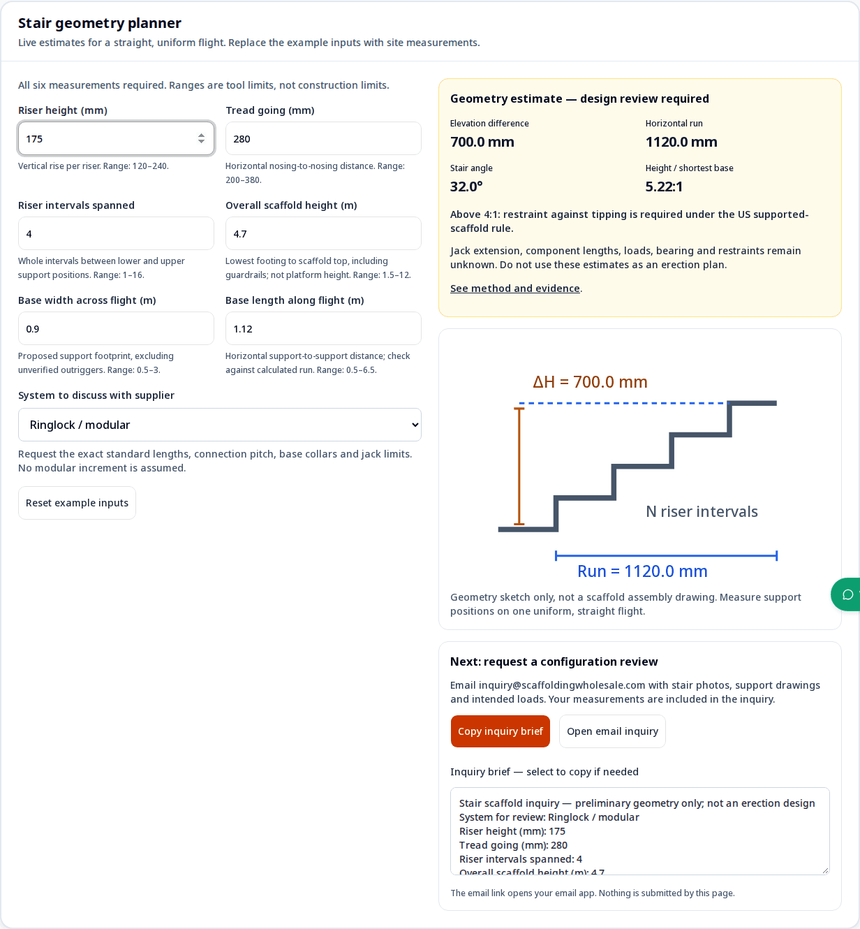
Straight, uniform flights only. Replace the example inputs.
Six inputs required; ranges are tool limits.
Vertical rise per riser. Range: 120–240.
Horizontal nosing-to-nosing distance. Range: 200–380.
Whole intervals between lower and upper support positions. Range: 1–16.
Lowest footing to scaffold top, including guardrails; not platform height. Range: 1.5–12.
Proposed support footprint, excluding unverified outriggers. Range: 0.5–3.
Horizontal support-to-support distance; check against calculated run. Range: 0.5–6.5.
Request the exact standard lengths, connection pitch, base collars and jack limits. No modular increment is assumed.
Above 4:1: restraint against tipping is required under the US supported-scaffold rule.
Jack extension, component lengths, loads, bearing and restraints remain unknown. Do not use these estimates as an erection plan. See method and evidence.
Email [email protected] with stair photos, support drawings and intended loads. Your measurements are included in the inquiry.
The email link opens your email app. Nothing is submitted by this page.
Scaffolding for stairs provides a level work platform over an existing staircase. Adjustable legs handle differences between support elevations only within a documented system configuration. Large differences may need unequal standards, purpose-made stair frames or a bespoke design. A general-purpose tower with longer feet is not automatically suitable.
For painting a straight flight, first compare a documented stair-tower kit with the task and available space. For multiple working lifts, unusual supports or heavy materials, ask an access contractor to compare modular and bespoke layouts. If you need people to walk between building levels, see scaffold access stairs; that is a different equipment brief.
| System | What distinguishes the arrangement | Next supplier question |
|---|---|---|
| Ringlock / modular | Exact standard lengths, connection pitch and base-collar geometry | Obtain a stair layout and manufacturer jack limits; a connection pitch does not guarantee leg compatibility. |
| Stair frames | Approved unequal frame or leg kit and locking details | Ask for the specific stair configuration drawing rather than substituting generic frame heights. |
| Aluminum tower | Model-specific stair kit, stabilisers and permitted height | Confirm the manual explicitly covers the proposed stair arrangement. |
| Tube and coupler | Designed geometry, coupler details and bracing | Request a layout and component schedule for this site; there is no universal modular offset. |
In US construction, scaffold design is assigned to a qualified person. Geometry alone cannot establish a buildable arrangement.
Footings must support the loaded scaffold. A surface finish or material name does not establish tread capacity.
Above 4:1, supported scaffolds need restraint against tipping. A lower ratio alone does not establish stability.
Tower instructions specify assembly, bracing, height and stabilisers. A generic adjustable leg is insufficient evidence of suitability on stairs.
These sources concern US construction and Great Britain respectively. They are not interchangeable global limits. Check the rules and adopted standards for the project location.
Use measured riser height and horizontal going for a uniform, straight flight. Count the riser intervals between proposed support positions. The defaults are an example; replace them before preparing your inquiry.
| Output | Formula | Worked example | Assumption or limitation |
|---|---|---|---|
| Elevation difference ΔH | N × riser height | 4 × 175 mm = 700 mm | N counts riser intervals between support positions, not visible treads. |
| Horizontal run | N × tread going | 4 × 280 mm = 1,120 mm | Going is the horizontal distance between successive nosings. |
| Stair angle | arctan(riser / going) | 32.0° for 175 / 280 | Uniform straight flight only; not a base-plate tilt setting. |
| Height/base screening ratio | Overall scaffold height / shortest base dimension | 3.6 m / 0.9 m = 4.0:1 | Include guardrails in overall height; measure from the lowest footing. |
The rise is an elevation difference, not a required jack extension. Equipment geometry, upper and lower jack settings, joints and connection levels must be resolved together. If base length differs from calculated run by more than 10 mm, the planner flags a survey check. That flag is an editorial screening threshold, not an installation tolerance. It cannot resolve feet placed on landings or irregular steps.
Results update immediately in your browser, with no remote calculation or loading delay. Empty, fractional-step and out-of-range inputs withhold all calculations. The inquiry can still request a survey and marks unresolved values as unconfirmed.
There is no product manual in this planner establishing extension, insertion or rated capacity for your equipment. Request those values for the exact jack and configuration. Diameter or total stem length alone cannot establish a safe setting.
Buckling resistance depends on section properties, effective length, end restraint, eccentricity and material behavior. An ideal Euler calculation does not supply a tested working-load rating for an unidentified threaded stem. No load curve or generic allowable extension is issued here.
For towers, follow the model-specific manual and assembly arrangement. HSE tower guidance explains the role of manufacturer instructions.
| Component | Required information | Current status |
|---|---|---|
| Base jacks / legs | Maximum extension, minimum insertion, capacity at extension and locking | Unknown until the exact product manual and loading are supplied. |
| Standards / frames | Available lengths, joints, bracing and platform connections | No leg length or quantity is selected by this planner. |
| Bearing / spreaders | Leg reactions, stair supports, spreader bending and slip restraint | No universal board thickness, mat or tread capacity assumed. |
| Ties / stabilisers | Design forces, verified support structure, attachment and layout | No anchor size, torque, tie count or interval generated. |
| Deck / protection | Platform rating, access, edge protection and falling-object controls | Task, local rules and system details determine requirements. |
A material label is not a capacity measurement. The quotation needs leg reactions and a verified route into the building structure. A board laid across different step levels can itself bridge, rock or bend; spreading load requires a designed support arrangement.
Do not treat a building-code design load as the measured reserve capacity of an existing tread. Similarly, a protective mat can protect a finish without proving slip resistance or bearing capacity. No universal spreader dimensions are specified here.
| Substrate | Survey information | Specific risk | Minimum next action |
|---|---|---|---|
| Timber | Tread thickness, condition, stringers and joints | Local tread bending or concealed deterioration | Seek structural review of reactions and support positions. |
| Concrete | Stair drawings, reinforcement, bearing and condition | Spalling, edge damage or unsupported precast details | Verify the load path; do not infer capacity from appearance. |
| Tile / stone finish | Structural substrate beneath the finish | Cracking or slipping even when the underlying stair is sound | Specify surface protection alongside a verified bearing design. |
| Steel grating / pans | Bearing bars, fixings, span and filled/unfilled status | Local deformation or an unsupported pan | Get the stair supplier’s structural information before loading. |
The screening ratio uses overall scaffold height from the lowest footing to the top, including guards, divided by the shorter proposed base dimension. Using only platform height or the wider side can hide a narrow-base problem.
The US rule identifies restraint above 4:1 and also addresses eccentric loads. Below that trigger, stability still needs checking against the actual design and system instructions. The planner cannot calculate tie positions, forces or anchor capacity.
Ask the designer to identify a verified supporting structure, connection product and restraint layout. Do not assume a stair handrail, drywall partition or friction prop is a suitable anchorage. See 1926.451(c)(1).
The least expensive component package may omit design, assembly, finish protection, access or reinstatement. Request comparable scope and hire duration in every quotation. No current supplier prices or delivery promises have been verified for this page.
| Option | Potential fit | Cost or complexity driver | Decision gate |
|---|---|---|---|
| Purpose-made stair tower | Repeat work within its documented stair configuration | Kit purchase/hire and transport; check stabiliser space | Choose only after matching the manual to the stair survey. |
| Modular scaffold | Multiple lifts or complex working areas | More components, handling and site design coordination | Compare access and load requirements with a designed layout. |
| Tube-and-coupler design | Irregular geometry outside standard kits | Greater design and skilled assembly effort | Obtain a site-specific design and assembly plan. |
| Work from a landing / alternative access | Task can be reached without supporting legs on treads | Reach limits, handling and floor capacity still matter | Have the access contractor assess a suitable alternative. |
Plan worker access to the deck separately from escape through the building. Confirm required route widths, headroom, door swings and protection with the responsible site and fire/building authority. These dimensions depend on jurisdiction, occupancy and site conditions; no universal walk-through clearance is calculated here.
OSHA 1926.34 requires unobstructed egress in its scope. A walk-through frame or overhead board alone does not demonstrate that a route is acceptable. Resolve falling-object controls and platform edge protection in the work plan; a label on a frame cannot do that review.
| Risk | Why it occurs | Mitigation or alternative |
|---|---|---|
| Misuse: extending legs to absorb the full stair drop | Unverified extension, eccentricity or inadequate insertion | Stop and obtain an approved leveling arrangement; do not improvise with loose blocks. |
| Cost: ordering from geometry alone | Missing ties, access units, protection or incompatible parts | Request an itemised quote after design review, including erection, hire duration and reinstatement. |
| Scene mismatch: ordinary tower in a stairwell | Insufficient width, kit coverage or safe assembly space | Compare a documented stair kit with bespoke scaffold or alternative access. |
| Occupied stairs: blocked escape route | Legs, braces or overhead work obstruct users | Resolve the route and protection plan with the site/fire authority before installation. |
| Case | Premise | Planner output or boundary | Action |
|---|---|---|---|
| Straight timber flight | 4 riser intervals; rise 175 mm; going 280 mm | ΔH 700 mm; run 1,120 mm; angle 32.0° | Send the support locations and stair drawings for bearing and equipment review. No jack size is selected. |
| Narrow concrete stairwell | Overall height 4.8 m; base 0.9 × 1.5 m | Screening ratio 5.33:1; above the US 4:1 trigger | Request a restraint design and confirm the supporting structure before procuring anchors. |
| Turning / spiral staircase | Riser and going vary between support positions | Uniform-flight calculator does not apply | Survey each support elevation and ask for a bespoke layout or alternative access method. |
Use the inquiry to collect missing information, then obtain the system configuration, bearing and restraint decisions before ordering. Assembly and alteration need the appropriate competent supervision. Record permitted loading, access arrangements and outstanding restrictions at handover.
In US construction, a competent person inspects before each work shift and after events that could affect integrity. See 1926.451(f)(3). A site tag or this planner’s output cannot replace that inspection. Review the plan whenever support conditions, loading or configuration change.
Published and maintained by Scaffolding Wholesale. This guide does not claim an independent engineering review. Reviewed November 1, 2026. Clause references below concern the stated jurisdictions. Review dates record source access, not a standard’s effective date. No claim of product certification or full legal compliance is made.
| Topic | Supported finding | Primary source / section |
|---|---|---|
| Design | Qualified-person design is required. | 1926.451(a)(6) |
| Restraint | More than 4:1 triggers restraint; eccentric loading also matters. | 1926.451(c)(1) |
| Foundation | Footings must be level, sound and capable of taking the load. | 1926.451(c)(2) |
| Inspection | A competent person checks before each shift and after integrity-affecting events. | 1926.451(f)(3) |
| System-specific rules | Frame and mobile scaffold provisions supplement the general rules. | 1926.452(c), (w) |
| Escape route | Maintain unobstructed egress; this does not specify a universal tunnel width. | 1926.34(a), (c) |
| UK planning | Use a recognised configuration or appropriate design calculations. | Scaffold design guidance |
US construction: design, foundations, stability, access and inspection.
US construction: additional frame, tube-and-coupler and mobile scaffold provisions.
US construction: unobstructed escape routes. Local building/fire rules also need checking.
Great Britain: planning, recognised configurations, bespoke design and competence.
Great Britain: tower manuals, stabilisers, assembly and inspection.
Review policy: recheck source clauses and the planner at least every six months, and whenever a source, method or supported range changes. Next scheduled review: May 1, 2027.
Unknowns remain explicit: product working loads, jack travel, stair capacity, tie forces, anchor selection, local egress dimensions and delivered equipment cost. Obtain manufacturer documents and the appropriate site review for each. Paid standards and certification records have not been verified, so they are not used to imply numeric limits or product approval.
A scaffold arrangement intended to provide a level work platform above an existing staircase. Its unequal support elevations must be accommodated by documented system components or a designed layout, rather than by tilting a normal scaffold.
A scaffold stair tower provides stairs for access between levels. Scaffolding for stairs supports a working platform over an existing staircase. Tell the supplier which task you need so that the quote covers the right equipment.
Count the riser intervals between the proposed lower and upper support positions. Four intervals at 175 mm produce 700 mm of elevation difference. Record actual elevations if the steps are uneven.
No. The calculator assumes one straight flight with uniform risers and going. Record each support coordinate and elevation for a site-specific review.
Use the exact manufacturer’s extension, insertion and capacity limits for the proposed loading and configuration. This page has no verified product data to establish a universal value. Send the model and manual to the designer.
No. The ratio is one stability comparison. Loading, base support, eccentric forces, restraints, assembly and manufacturer requirements remain unresolved by this tool. See the stability evidence in the guide.
No. A spreader cannot establish the capacity of the tread, its connections or the stair supports. Have the load reactions and bearing arrangement checked together; finish protection alone does not provide structural verification.
Ask the manufacturer whether the exact model has a documented stair configuration. Do not substitute generic adjustable feet for a missing stair kit or move a tower along a stair flight.
The planner cannot determine either. The designer needs the scaffold arrangement, forces, supporting structure and product data to specify restraint and connections. Avoid ordering anchors from the height/base ratio alone.
Only after the site has resolved the required escape route, access clearances and protection from overhead work with the responsible authority. A walk-through frame label alone is insufficient.
Ask for the configuration drawing, itemised component list, manuals, permitted loading, bearings, restraints, access, protection, delivery, assembly responsibilities and hire duration. Include stair photos and measured support positions.
Use the general inquiry below and request a site survey. The planner also provides an editable inquiry brief; invalid inputs are excluded from its calculated results.
Send country, site photos, stair/support drawings, measured support positions, target platform elevation, overall height, intended loads and escape-route constraints. If anything is unknown, request a survey before an equipment schedule. Use the planner’s brief to carry your measurements into the inquiry.
Priority inquiry email
Ask for a documented configuration and itemised quotation. The email link opens your email app; attach photos and drawings there.